Monday, April 30, 2018

Work Installing Condenser and Piping

Work Installing Condenser, Fan Mount and Tubing
Date: 4.28.18
Location: Logan HS
Time: 5 hours
Goal: Install the condenser module, run wires and tubing and work on fan mount.
Students: Austin, Paige, Alex and Caitlin

The condenser installation was not easy! It needed to be manipulated in such a way as to allow the tubing and wires to be oriented toward the pumps, reservoirs and electrical panel. Care had to be taken with the micro vibration motors so as not to disconnect one. It was almost 2 hours to get this unit fitted with all the holes drilled and the orientation correct.

Once that was in, running the tubing to the peltiers went smoothly. We still have to finish that work.

Portholes were cut in and seemed to allow adequate visionary access to the tanks. Electrical diagrams were drafted and work started on the mount for the fan motor. The fan motor mount is proving to be a challenge due to where it has to be located (on the elbow of a PVC pipe).

We feel we are close to a pump test this week which would be a "milestone event" as we need to check for leaks and water flow. We also are ready to start work on the wireless transmitter to capture a video image of the controls. We are going to try a Rasberry Pi3 for this application.

A future goal is to run all the wires into switches and fuse box.


Austin applying silicone on the micro vibration motors. to seal them up from water.

Condenser tank off the cart and holes marked out for drilling.

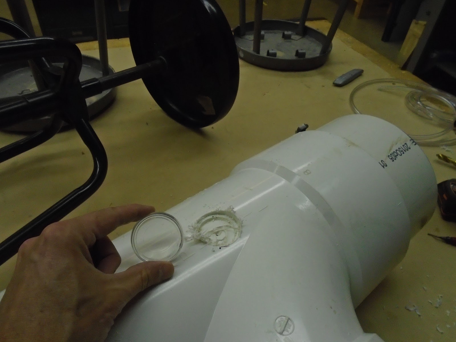
Porthole being drilled in with a plastic furniture leg carpet protector as our "porthole". 

We used a dremel tool to cut in the hole and then siliconed the porthole in.

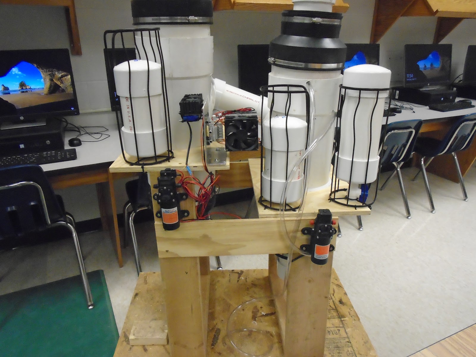
Condenser module with the wiring and tubing completed. If we posted a picture of this by itself on the Internet, we wonder how many people would guess what it is.

Condenser module installed in the tank. This picture is looking up from the bottom. Notice how wires are zip tied to protect them. The bottom of the condenser unit is siliconed to the PVC tank to force air flow through the radiators.

Top view of condenser module installed.

View showing porthole installed so students can see the water flow out of the condenser module.
A LED will be used to light up the tank.

Electrical box installed in the lower front for us to run wires into.

Draft of electrical schematic.

Draft of additional electrical schematic.


Video of the Condenser Module. Notice the two holes in the plexiglass on either end
of the radiator which are to allow a small amount of air flow to drop to the bottom
condenser unit. We hope both radiator will be utilized more efficiently that way.

Salt water tank inlet was drilled and tapped into the PVC tank. The hose will connect to the 3/8" barb.

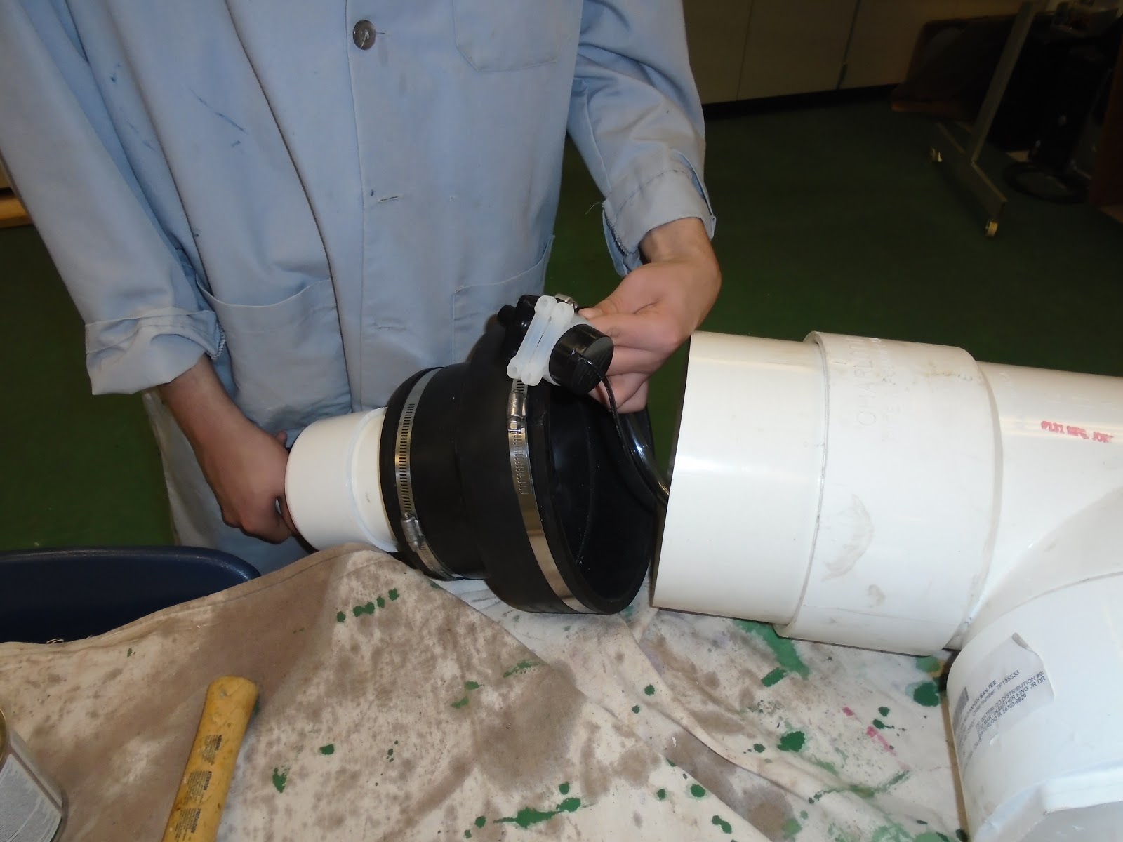
The fan motor bracket has to be square with the 4" pipe it is running into. This proved to be a challenge to machine.

Aligning the main shaft for the fan and fan motor.

Raw materials and 12 V DC fan motor for mount.

Cutting out the fan mount. The two flanges will be bent to the circumference of the 4" elbow.


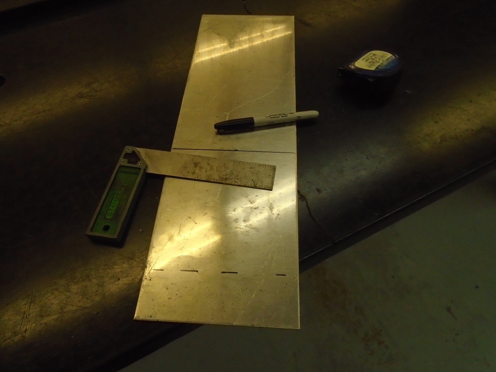
Completed fan mount bracket with holes drilled for motor. We created a paper template to transfer
the pilot holes to the aluminum plate.


On the evaporator side, we cut in holes to hang the eventual shower head.


Friday, April 27, 2018

Micro Vibration Motor work and Delay Circuit

Micro Vibration Motor work and Delay Circuit
Date:4.26.18
Location: Logan HS
Time: 3 hours after school
Students: Dom and Andy (Paige and Austin helped on Friday)
Goal: Get the Micro Vibration Motors attached and timer system completed.

The work night tonight was a mixed. We moved forward in some areas and back in others. We wanted to test out the motor delay circuit to help remove water from the radiators. When installing the micro vibration motors, one of the connections snapped off. The wires on the motor are small (I would guess 30 gauge) and difficult to solder so it came as no surprise it happened, it just means we have to solder on another motor.

The delay circuit needed more time to test that anticipated. We had the fundamentals worked out but the voltage output to the 555 timer (in the voltage divider circuit) and the rest of the circuit was to low. Mr. Foye worked with Andy to rewire the circuit as we needed to increase it to 12 v which was done by using some different resistors. Once on the breadboard, the circuit preformed well. Andy will take the circuit and solder it to a circuit board on Friday.

We needed to make another evaporator side peltier module. This was almost completed except for the heat shielding around the wires.

I think we are ready to install the condenser module in the tank now. The prep for that will take place over the weekend.


Dom soldering the 18 ga extension wires on the peltiers.

Testing the micro vibration motor circuit Andy designed.

Micro vibration motor installed on the condenser. If someone just looked at this module, I pretty sure they would have no idea what it was for.

Some design calculations and considerations for the electrical wiring schematic.

Paige soldering the fan wires for peltiers.


Wednesday, April 25, 2018

Soldering Connections and Evaporator Peltier Work

Soldering Connections and Evaporator Module - Peltier Assembly
Date: 4.25.18
Location: Logan HS
Time: 1.5 hours
Students: Paige, Caitlin, Alex and Gabe
Goal: Begin soldering extension wires on pumps and get peltier for evaporator ready.

We took some class time today to work on the DM. The students that were ahead had completed their state machine on Multisim helped out getting wires soldered, PVC pipe inlets and outlets glued and the evaporator peltier module ready.

We needed a day like this to get some of the detail work done that just takes time to do. A work night is still planned for Thursday night.


A frame for our control board has been made out of plywood.

A piece of plexiglass over the top of the control board allows students to see wiring and is easy to drill through. This will be mounted on the DM soon as we need to begin hooking up switches.

Alex using epoxy to glue in the hose barbs in the condenser and evaporator reservoir tanks.

Paige and Caitlin soldering up extension wires on the two pumps.

Gabe reinforcing the wires running from the peltier with shrink wrap and then foil tape to resist heat. This will be part of the evaporator module so we expect it to heat up considerably and we wanted to protect the wires.

Gabe putting on Arctic Silver Thermal Paste on the hot side of the peltier chip. We hope to improve the thermal conductivity. The thermal paste is thick and difficult to work with and clean up.


Monday, April 23, 2018

Fabrication of Peltier Cooling Unit

Fabrication of Peltier Cooling Unit
Date: 4.21.18
Location: Logan HS
Goal: Fabricate peltier Cooling Unit
Time: 2.5 hours

Work progresses on the DM with fabrication of the mounts for the peltier modules. Quite a bit of time has been spend in hardware stores finding alternate parts for an application. For example, we need a "porthole" that will be drilled into the DM so people can see inside the tanks. We found some transparent plastic furniture coasters that we think will work after we silicone them in place.

We also need a shower head on the evaporator side to spray the salt water over the flow down matrix. As you can see from the picture below, we need to experiment with a few different types to see which one will give us the best spray option.

Also, we are beginning work on using a Rasberry Pi with camera to show our instrumentation. The solar panel is in and a mount is being created for it. We are setting the angle of the panel to about 16 degrees. The angle changes with latitude and we arbitrarily picked Puerto Rico as a destination for the DM. Puerto Rico is at 18.2 degrees latitude. Below 25 degrees you have to take a multiplier of .87 to calculate the angle of the panel. This came out to 15.8 degrees.

A future goal will be to hook up the hoses and install the condenser. We hope to start running some electrical wires to controls this week.


Different types of lawn a garden and regular shower heads.

Raw material for the evaporator peltier module mount.

Mount is fabricated and ready to be drilled to our specs.

The longer bolts sticking out on the left will be for the peltier and water block to sit on.

The two cooling peltiers are mounted and installed. Ready to be connected.

Top view of cooling condenser module.

View of where we are at so far in the fabrication process.

Aluminum plates machined and bolted together with the block we are using for heating the evaporator.
Peltiers still need to be installed in this module with thermal paste.


Our 12 V solar panel has arrived. We are using a small one as a proof of concept. A mount is being made for it.


Friday, April 20, 2018

Work Night on Evaporator 4.19.18

Work Night on Evaporator
Date: 4.19.18
Location: Logan HS
Time: 2.5 hours
Goal: Seal up PVC pipes, reservoirs and work on surface tension vibration units.
Students: Austin and Dom

Tonight we worked on cementing up PVC pipes to seal them up for future water tests. We also had to solder the extension wires on to the new cell phone vibration motors we purchased to decrease the surface tension of the radiators on the condenser side of the DM. These motors proved difficult to solder because of the small diameter of the wire and we ended up losing one of them.

After each one was soldered they were checked with a 3v power supply to make sure they were functional. We know from testing they will cause a vibration on the radiators, we don't know if it is enough to break the surface tension.

Alex also started work on the fan motor assembly. We are still working out the details of this, but we  want a support inside the pipe so fan blades do not hit the inside of the pipe. We used a plastic mesh and epoxy for this.

Our goal next week is to do a test on the evaporator side of the DM. We should have the peltier wired in allow us to see what temp we can get the evaporator to.

Note: We did at test of the radiator vibration system the next day and it seemed to work! A video is posted below for you to view.

Alex fitting the plastic mesh to support the fan motor.

We used Marine epoxy to fill in a center cell. This will eventually be drilled out
to support the fan shaft.

Dom cementing the PVC pipe lower drain assembly.

Dom placing the submersible pump in the bottom of the evaporator tank.


This is one of the micro vibration motors that they use in cellphones. We decided to try some of these
to vibrate the water drops.


This is one of the micro vibration motors after some mistakes soldering and experimenting with the best
way to support the wires. We will have to order another one.


Austin with one of the micro vibration motors and he soldered wire extension.
They are heat shrinked twice to help support and improve waterproofing.


Dry testing the micro vibration motors to make sure they will vibrate the surface.
They do, in fact you can even feel the support structure vibrating.

This is a (somewhat blurry) video of our micro vibration motor test the next day. We poured some water over the radiators then angled the condensor unit to simulate its position in the tank. As you can see, the water droplets were releasing and dripping off. We experimented with a motor delay (10 sec. on 10 sec. off) and had mixed results. We also tested a 3 sec. on 3 sec. off burst and had better result. A 555 timer circuit is being design for this application.


Progress shown on pump installation and reservoir tanks installed.


Saturday, April 14, 2018

Installation of Evaporator (Flow Down Matrix)

Installation of Evaporator (Flow Down Matrix)
 Date: 4.14.18
Location: Logan HS
Time: 2 hours
Goal: Install the flow down matrix in the 8" PVC Tee and tap out holes for cutoff valves.

The first thing that needed to be done was to drill and tap out the holes where the valves would be placed. We again used plastic fitting with a threaded nipple that would turn into the valve. A simple way to do this was to just drill a hole and silicone it the valve in. We try to stress the importance of craftsmanship so we drilled and then tapped the hole so the threaded nipple would easily thread into the PVC end cap and then enough threads were exposed on the other side to thread on the valve. It takes longer to do, but it will be stronger and more reliable.

The next step was to install the flow down matrix. Measurements were taken and two 1/4" aluminum rods were cut and installed into the holes that were drilled in the evaporator tank. This will provide a very good support structure so the flow down matrix can't drop down, yet still allowing for a nice water flow.

Holes were then measured and drilled into the PVC pipe for the inlet and outlet hoses. This went well although consideration had to be made for the location of the fernco and where the salt water sprinkler head would be located.

Our next goal will be to install the pump and get the evaporator side working. We will also work on a vibration solution for the condenser side.


Tapping in treads for the plastic fitting.

Completed end cap with valve.

All three end caps done.

Notice the aluminum rod to the right. This is being measured before cutting.

Both aluminum rods in place to support the flow down matrix.

Flow down matrix installed except for upper hose.

Holes are cut for the inlet and outlet hoses. We are ready to hook it up to a pump and reservoir.


Desalination Project Completion

LA CROSSE LOGAN HIGH SCHOOL DESALINATION MACHINE PROJECT Designed and Fabricated in the Logan Technology & Engineering Department  ...