Saturday, April 14, 2018

Work Night on Evaporator and Sensor Array

Evaporator and Sensor Array Work Night

Date:4.2.18
Location: Logan HS
Time: 4:00-7:00 PM
Goal: Finish the evaporator and test thermistor sensor array.
Students: Dom, Andy, Alex and Paige

The work night produced mixed results. We fabricated the matrix for the evaporator side of the Desalination Machine (DM). It came together nicely and when we did a water test all connections held. The condenser on the other hand, produced problems right away.

When water was run across the radiators it would hang up and not drip off due to surface tension. This is a big concern because we need it to freely drip down to the clean water collection chamber. We think the issue is surface tension and the fact that the radiators are very tightly designed which makes it difficult to allow water to release. We are going to look at designing an acoustic vibration device to vibrate the drops off the radiators or some type of motor that when activated will vibrate the condenser.

On the electronics side of the DM, Andy was having problems with the temperature sensors. There was a very big discrepancy in the temperature both thermistors were outputting. He worked with Mr. Foye to break down the circuit and see if the problem was hardware or software. After about an hour of testing, we decided to replace the Arduino Uno for a newer one to see if that changed anything. They next day in class, Andy replaced the Uno and the circuit seemed to work giving off values within the tolerance range.

Next goal is to install the evaporator and start fabricating valves for water movement.


Testing the condenser to see how water behaves on it. We had problems here.

Dom working on zip ties on the evaporator flow done matrix.

Mr. Foye and Andy working on the thermistors for temperature.

Dom cutting out the flow down matrix support material with a Dremel tool.

Water testing the flow down matrix for leaks. No leaks!

Testing the condenser side for leaks. We had two, but were able to tighten the hose clamps and seal them.


Dom cutting with a dremel tool.


Water testing the flow down matrix.


Sunday, April 8, 2018

Fabrication of Flow Down Matrix and Condensor


Fabrication of Flow Down Matrix and Condenser

Date: 4.7.18
Location: Logan HS
Time: 2 hours
Goal: Create a flow down matrix for the evaporator side of the Desalination Machine (DS) and finish up the condenser.

With the condenser almost finished, work began on the flow down matrix which is going to be used to evaporate the saltwater. We had some materials donated that were helpful in the fabrication of the matrix. We estimate that we need three layers to evaporate the saltwater being sprayed down and over it. We are unsure of how the tubing we have will work. The sidewall is thicker on the 3/8" clear tubing which will effect the amount of heat it radiates. Thinner sidewall tubing seems to bubble up and was difficult to keep stable. We hope to have most of this unit assembled next week and would like to test air and water flow the following week.

Our next goal is to finish the matrix and then begin work on the supply reservoirs that are needed for the condenser and evaporator. Much time has been spent in local hardware stores looking for the proper fittings to connect all the different hoses and pumps.

Paige is putting on silicon to seal up the radiators we will use in the condenser unit.

Trouble...the 3/8" tubing is kinking when we make a bend. We need a solution.

We ordered some stainless "U" pipes that will help us make the tight turn we need
without kinking. It seems to work well without taking up much space. The shorter
we keep the tubing, the less heat/cold loss we will have.

Support material is a plastic grid that was donated to us by Mr. Foye. It was marked to the
size of the 8" Tee then cut on the bandsaw.

The 3/8" hose is being spiraled around the grid and then zip tied down to secure it.

One layer of the matrix is made with a stainless "U" to keep the hose
from kinking in a tight turn. The next layer will be placed on top of this.


Sketch of the possible locations of reservoirs, controls and sensors.


Thursday, March 29, 2018

Fabricating Condenser Module

Date: 3.29.18
Location: Logan HS
Time: 3 hours
Goal: Fabricate the support structure we are calling the condenser module that will house the two radiators.

We worked on the "condenser module" today and got it roughed out. This took a while to fabricate as it had lot of angles and special cuts.

 We used some 6" PVC pipe as supports and may put a couple more supports on the sides. The module has some temporary screws to hold the plexiglass in place as the silicon on the top cures. The bottom piece of plexiglass is not glued in anyway (just a couple of screws holding it in place) in case we need to modify.  We will put the radiators in and get everything secured with silicon later.

No holes are drilled in the top plexiglass for airflow to get to the bottom radiator yet except for one for the radiator hose to go down through. We are still determining the size of the holes and how many we need. We want the warm air flow to move through the top radiator and then to the lower one to increase the amount of condensation that we hope will occur.

We will use a Dremel tool later to cut a hole in the bottom plexiglass to allow water to run down to the collection unit.

Next objective is to begin work on the evaporator module.


Revised sketches of what we thought could work as a condenser module. This led us to our current design.

More sketch ideas on the condenser and evaporator units.


Raw material being measured and cut out.


Second piece of plexiglass was cut out and PVC pipe was cut at angles.


View from the side with the PC radiator we are planning to use.


Top view of radiator.


Side view of roughed out condenser module. When installed in the pipe, it will give our radiators the angle
we want to maximize condensation.


A little hard to see, but this is a picture of the condenser module (without radiators)
placed in the  pipe above the "T" air return on the left. You can see the bottom piece of
plexiglass and how it fits to the angle and shape of the pipe. The ruler is on the right to hold it in the pipe
 for the photo. Eventually this will be sealed with silicon or plumbers caulk. 

Saturday, March 24, 2018

Working on Cooling Tank 3.24.18

Date: 3.24.18
Location: Logan HS
Time: 3 hours
Goal: Fabricate a plexiglass support structure for the radiator that we are using in the cooling tank.

After the Thursday work night we needed to make up some ground on mounting the radiator in the cooling tank. The problem we had to deal with is the angle it needed to be placed at and how to support it with a material that would be safe when clean drinking water comes in contact with it.

This is just a single radiator and we wanted to use two. We may need to add a system of cooling tubes to supplement the radiator if we are not cooling the air enough.

The steps below take you through the fabrication process of what we hope will be a successful solution.

A cardboard cutout was cut to fit in the 8" pipe to help us determine the angle. We would use as a template
for cutting the plexiglass.

Cardboard template is used to trace pattern onto the plexiglass.

The plexiglass is rough cut on a bandsaw and then later sanded down to fit the inside of the pipe.
Radiator pattern was traced onto the plexiglass.

The plexiglass was put in a vice and a Dremel tool was used to cut out the shape of the radiator.


Radiator is fit into cutout and silicon caulk will be used to seal around the edges.
The duct tape at the bottom of the photo is just so we can hold up the bottom
edge of the plexiglass when we insert it in the tank. 

Work Night 3.22.18 on Desalination Machine

Date: 3.23.18
Time: 4:30-7:00 PM
Location: Logan HS
Time: 2.5 hours
Goal: Put new wheels on Desalination Machine and work on the chiller side of the cooling system.
Students: Dom, Austin, Ian, Caitlin, Cashew, Gabe, Matt, Boy Yang and Joel.

It was one of those nights were our testing revealed more failures than successes. The new wheels on the cart were mounted with no problems and work well. They are bigger wheels that will support the weight of the DM over uneven surfaces better.

Work began on the "cold" side of the DM tank. We wanted to use two PC radiators in the 8" pipe to cool the warm vapor that will be transferred from the hot tank. After looking at multiple variations, we found we could not get both radiators in the pipe at the angles we needed to support the best cooling in order to get condensation to occur. There is not enough room to pipe water into two of them at the same time.

We then began to construct a single radiator solution which will work, but we are unsure if we can get the temperatures we want with just one. An idea is to supplement the 1 radiator by running additional tubing in the cold tank that the cooled water can run through. This would be supported by a plexiglass infastructure.

Next work night will be spent on fabricating this system for the cold tank side of the DM.


Getting ready to put new wheels on the temporary cart we built for the DM.

Dom adding the wheels.

Austin and Dom fabricating support structure for the radiators. We could not get the
right angles in the space we had to work with in using two radiators.

Here you see one of the radiators we are using and some of the plexiglass and support structures
we were experimenting with. We decided to use plexiglass as opposed to aluminum on the clean  (cold) water tank.


Dom drilling some holes for wheels.


Monday, March 19, 2018

Base Fabricated for Desalination Machine

Date: 3.17.18
Location: Logan HS
Time: 3 hours
Goal: Design and fabricate a base to support the Desalination Machine (DM) in its position of function.

We had the DM stored in our upper storage area of the shop and it was very cumbersome to move back and forth when we wanted to work on it. We needed to build a base to make it more easy to transport and get an idea of what the final "cart base" could look like. This is a temporary base as we will eventually make a new one out of aluminum.

Some design considerations we had was to make sure the DM was supported in the position of function, put it on wheels for mobility and leave room at the bottom for hoses and valves to hook up.


Tank supports cut out a little 8".

Plywood tank supports tested for size.

Side view of completed cart.

Front view of cart.

Top view of cart. We have room to mount our electronics and pump reservoirs on the plywood supports.

Wednesday, March 14, 2018

PVC Redesign for Desalination Machine

PVC Redesign for Desalination Machine

Date:3.14.18
Time: 1 hour
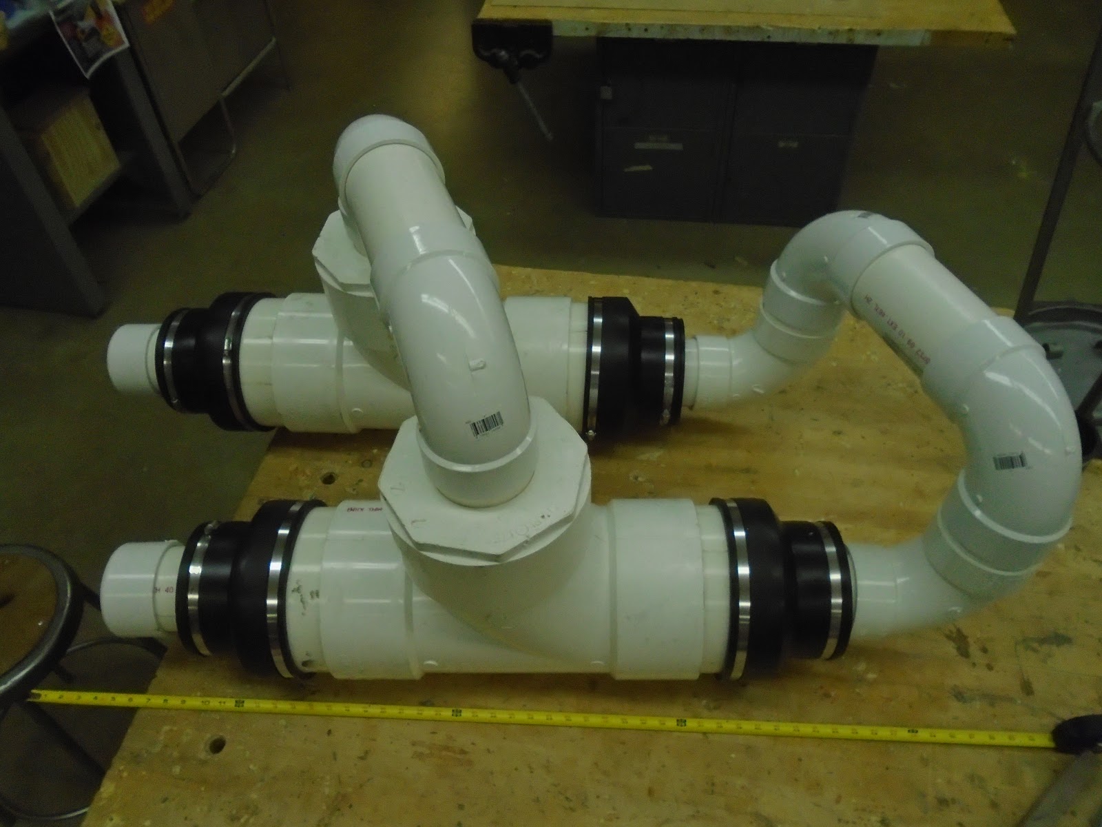
Goal: Re-cut PVC pipes and add 90 degree elbows to decrease size of Desalination Machine (DM) and improve air flow.

We decided the weight of the DM was getting too great as well as the overall size. We needed to come up with a new way to route the PVC pipes to minimize size and maximize flow. The arrangement you see below reduced weight by 15% and we hope will improve the flow rate by decreasing the distance between the hot and cold tanks.

We still have to make a cart to hold the DM upright. That will be built after we finalize the size/shape of the machine. None of the pipes are cemented in right now which allows us to modify as needed. The down side is moving the DM back and forth storage causes pipes and elbows to come off.

Our next goal is to work out the heating and cooling mechanism for the tanks.


Side view of DM.


Top view of DM.
The plan is to have the tank (8" T) on the left be our hot tank and the one of the right be our cold tank. 


Top to right side angle photo. 

Desalination Project Completion

LA CROSSE LOGAN HIGH SCHOOL DESALINATION MACHINE PROJECT Designed and Fabricated in the Logan Technology & Engineering Department  ...